
Introduction#
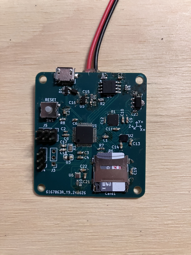
This is the first iteration of the control board that I designed and assembled myself. It is meant to record data and control a model rocket during its flight to help it reach the desired altitude.
Components#
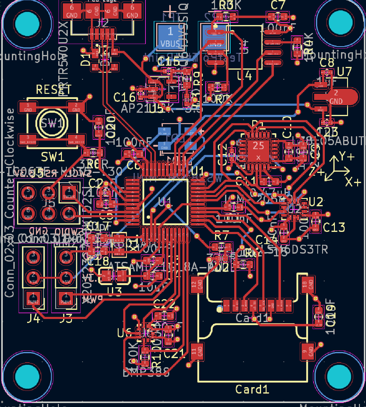
For the main processor I decided to use the ATSAMD21 microcontroller. This was mostly because it was pretty powerful, came in a QFP package and has been used in many arduino and other open source boards.
Some of the other components that I needed included:
| Component | IC Used |
|---|---|
Barometer | BMP388 |
Accelerometer/Gyroscope | LSM6DS3TR and ICM-20689 |
SD card tray | Clamshell Tray |
Power management | L78L05ABUTR and AP2112K-3.3 |
Servo header | 3-pin Header |
Backup NAND flash | W25Q64JVSSIQ |
I decided to use two accelerometer/gyroscopes because the LSM6DS3TR is widely used with great support, but not quite as accurate as the ICM-20689. I was able to get both working, and in the end there wasn’t much need for the LSM6DS3TR other than to confirm the data seen in the main gyro/acc.
I also added a NAND flash with the idea that I could write to it as well as the SD card during the flight in case something happened to the SD card, but There was never much need to use it and after verifying that it worked I never implemented it in the code.
Design#
I used Kicad to create the schematic and board layout.

Board Bringup#
Once the soldering was done, I had to burn a bootloader onto the board. I exposed the pins for serial wire debug, which is what I used to do this. Normally, you have to use another board with a ATSAMD21 processor to burn the bootloader, but I was able to use a Raspberry Pi Pico since their microcontrollers are similar enough. This allowed me to flash the bootloader and then use the MicroUSB port to upload code.
At first, some of the chips were not detected but I was able to fix all of these problems by reflowing them again and fixing some soldering joints. Eventually I was able to get all of the peripherals on the board working and recording data.